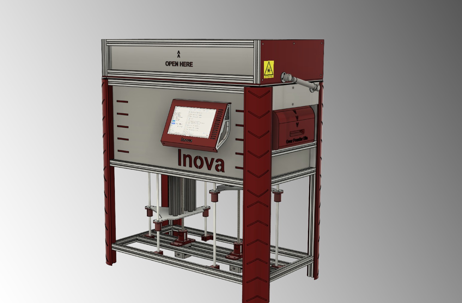
Once I have finished the state-of-the-art search in the field of SLS printing, printers and related DIY projects I moved to first step of the project – features definition and Fusion 360 3D Printer Design. Having in mind I want to have the printer not to be slower than FDM printers, making nice complex prints and be user friendly, I had to make some decisions which later affected the Inova’s design a lot. But I haven’t realized about it that time. So, how will my printer look like?
Two chambers and roller
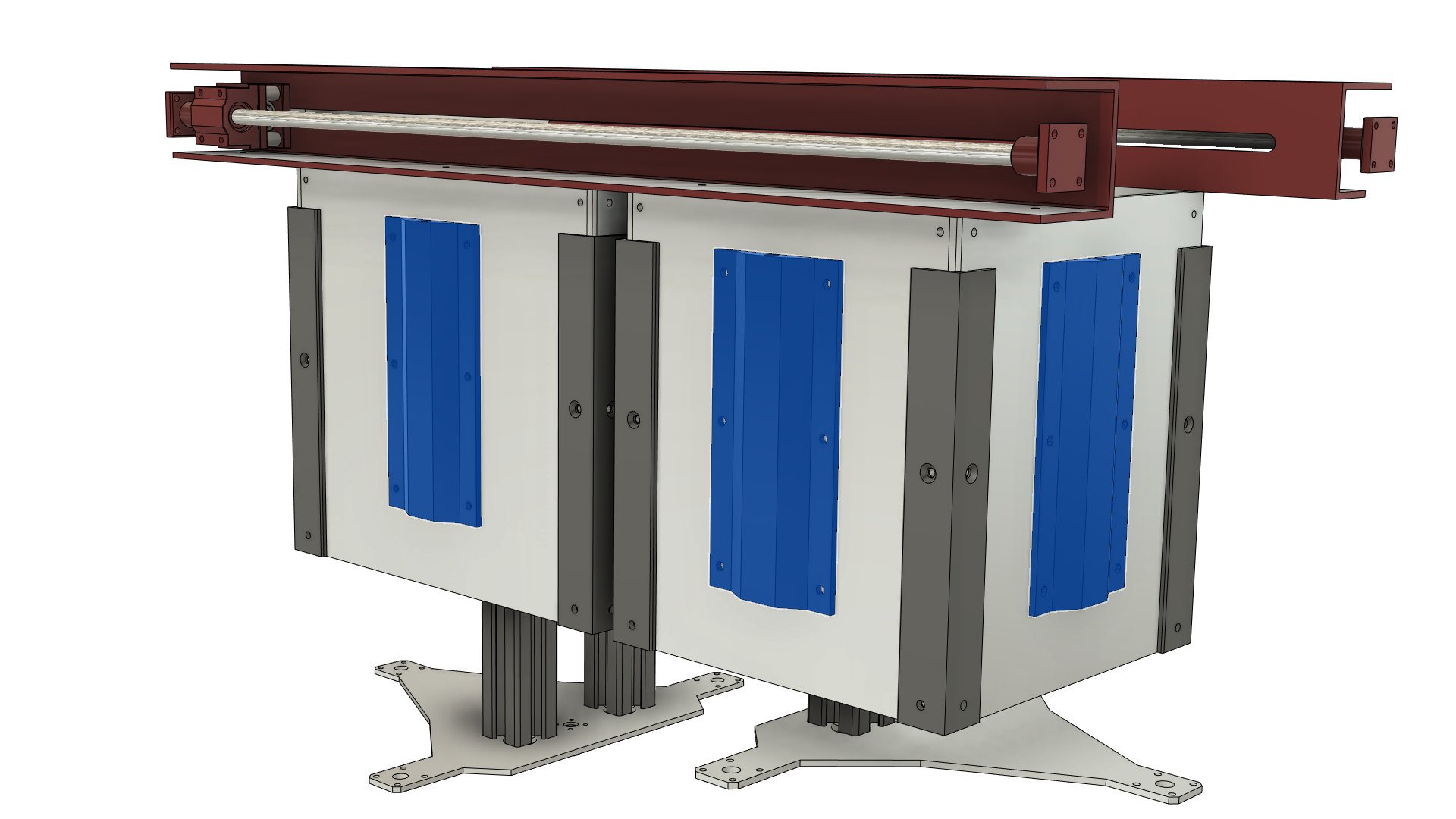
I decided to use the ordinary arrangement of the SLS printers. It means to have two chambers with the moving beds. One as the powder reservoir (powder chamber) and the second one for the printing outputs (print chamber). The printing material (PA12 powder) will be moved layer by layer from the powder to print chamber using wiping mechanism.
I decided to go in the way of counter rolling mechanism instead of simple piece of aluminum plate. I choose this way because the quality of the layers is one of the parameters directly affecting printing quality. The Fusion 360 model of these mechanical parts is on the following picture.
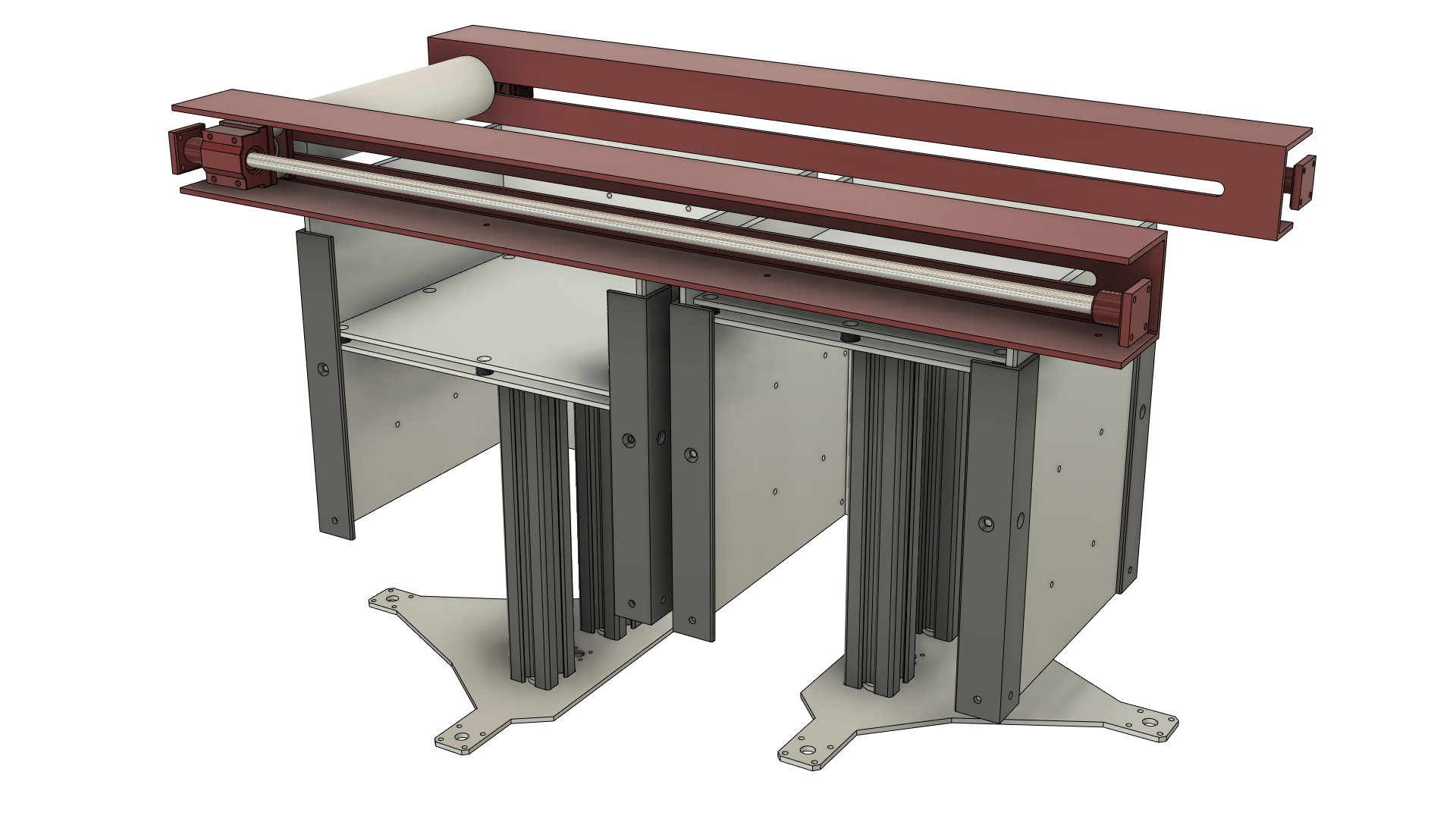
The dimensions of the chambers are 220x175x200 mm for the powder reservoir and 175x175x200 mm for the print chamber. It should allow me to print the range form small to mid-sized parts. I would like to have the effective volume somewhere like 150x150x180mm.
In FDM technology depends the size of the PLA or PET-G prints on the effective printer bed size and height of Z-axis. You don’t have to care much about anything else. In SLS world the bigger the part is bigger problems related to the temperature management you face. You can image it as printing big ABS parts at FDM printer, but much worst. Bigger sintered area in one layer implies in bigger tendency to warping and shrinking. You must control not only the temperatures while printing/sintering the parts, but also after the print is complete. The right setup of the time and temperature relation is the key while cooling parts down.
Heating control
Due to these facts, I proposed quite comprehensive heating system. It’s true that it can be seen as an overkill, but hopefully, it will do what it should. I want to achieve maximal temperature uniformity possible across the material in both powder and print chamber. It means I want to have the temperature control on every side of both chambers, including the beds.
Why such a robust solution? In the powder chamber the PA12 other material used for printing must be preheated in the whole its volume. Then it will be wiped to the printing area on the top of the printer chamber. Infrared or halogen heaters will heat the top layer approx. 10°C under PA12 melting point, which is approx. 182°C. These heaters represent the final but important step in the pre-sintering procedure. It also implies need for another quite specific temp control loop.
Once the printing process finishes, cooling process starts. Here you want to cool your prints down quite slowly and uniformly otherwise you can say goodbye to shape and dimensional accuracy. So, I had another problem on the way. I needed 10 independent temps’ inputs to control just for chambers. And to make things worse, at least another one for surface temp control just before laser comes on stage.
Galvo at scene – X, Y axis
I want my printer to be quicker that FDM ones. Therefore, I had to avoid common Cartesian X and Y axis layout. Why? Even if the X and Y moves would be at the same decent speeds as the FDM printers do, total print speed will be much slower because of layer preparation time overhead. Therefore, I decided to go in a way of galvanometers (galvos). Unfortunately, it kicked me back on the Google and meant another heap of reading.
The galvo use in DIY printer projects was to me anything, but not straightforward. Just one example – it is not an issue to make galvo move the laser beam along the print bed. Problem is to make the laser beam moving with the geometrical accuracy of a few tenth of millimeters. Or at least for me it really was the problem.
Laser source
When speaking about the laser, its source will be 5W blue laser diode (wavelength of 445 nm). It is the most cost-effective solution but as with anything, you pay for its low price in another way. This mostly relates to the shape of the laser beam source and specifics while focusing it – especially for the relatively long distance. I will for sure write something more about laser optics I used in the separate post.
Frame
Final part of this post is about the frame construction. I made it from the so called 2020 extruded aluminum profiles (20x20mm),
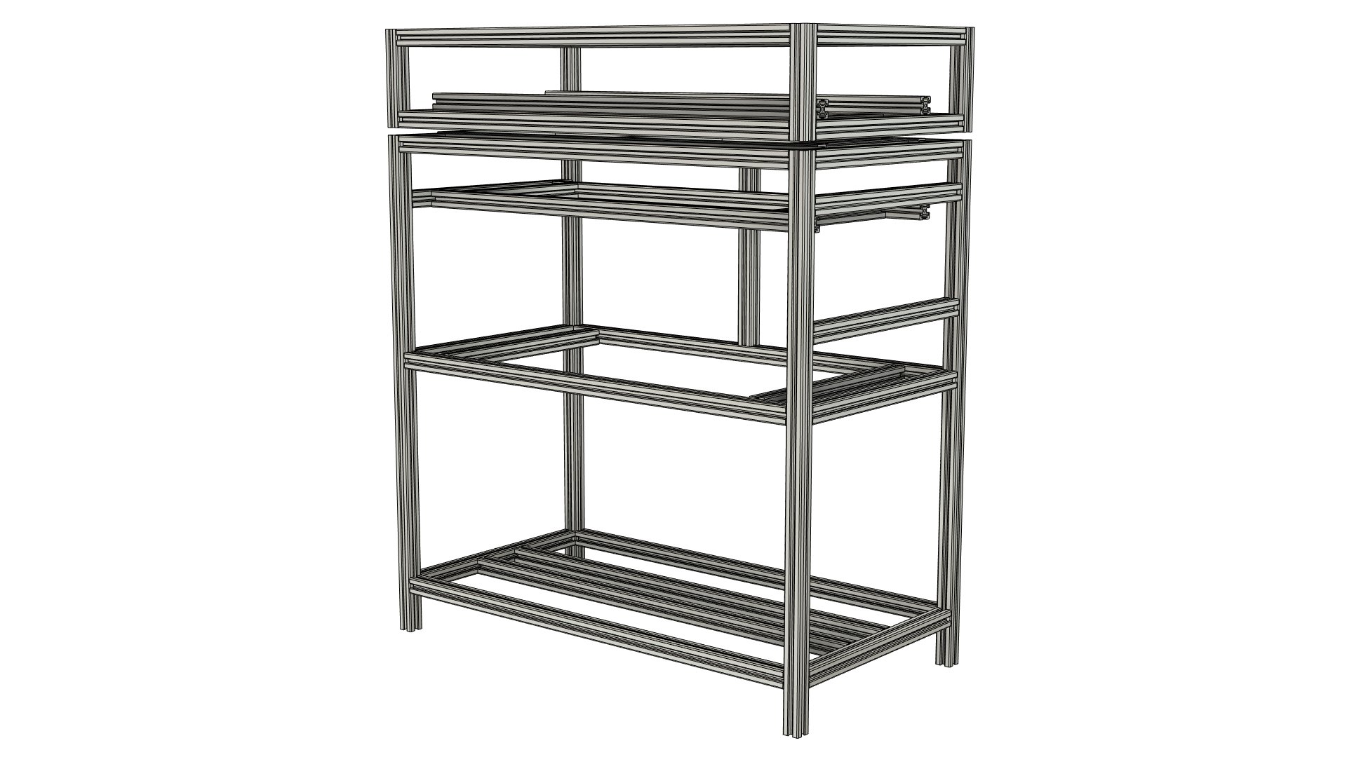
and all the walls are from the 3mm thick aluminum plates. It is quite common approach in the DIY project of this kind, resp. Fusion 360 3D printer design.
Reason is that aluminum is easy to machine, has excellent temperature conductivity and is heat resistant up to high temperatures. Therefore, it is ideal for the frame construction as well as for chambers heating. Sadly, it is also problematic for the same reason. Electronics suffer in hot environment and safety to use (chambers will be preheated to approx. 150°C) is also an issue. Even though I designed the frame as two-skin I had some troubles with the heat in early stage. Removal of temperature bridges, resp. their weakening is the must. The Teflon (PTFE) is used at meaningful frame joints and the rock wool insulates the top skin form the inside heat. But to be honest I am not happy with my current design, but at this development stage I will leave it as it is.
Before I finish for today, I would like to summarize the key design parameters I have defined so far:
- Print chamber volume: 175 x 175 x 200 mm
- Effective print volume: 150 x 150 x 180mm
- Powder reservoir volume: 220 x 175 x 200 mm
- Laser source: 5W blue laser diode (wavelength 445 nm)
- Layer application mechanism: counter rolling roller
- Temperature control: powder chamber with 4 independent elements, powder bed, print chamber with 4 independent elements, print bed, print area surface using 4 heating elements
- Main construction material: extruded aluminum profiles (2020) with aluminum plates – double skin
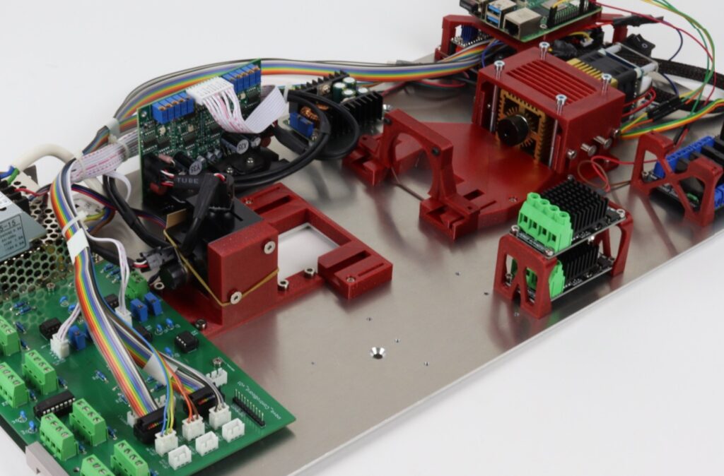
So, that’s it. In the next post, I will focus on the electronics and the firmware selection.
—
Join us on Discord