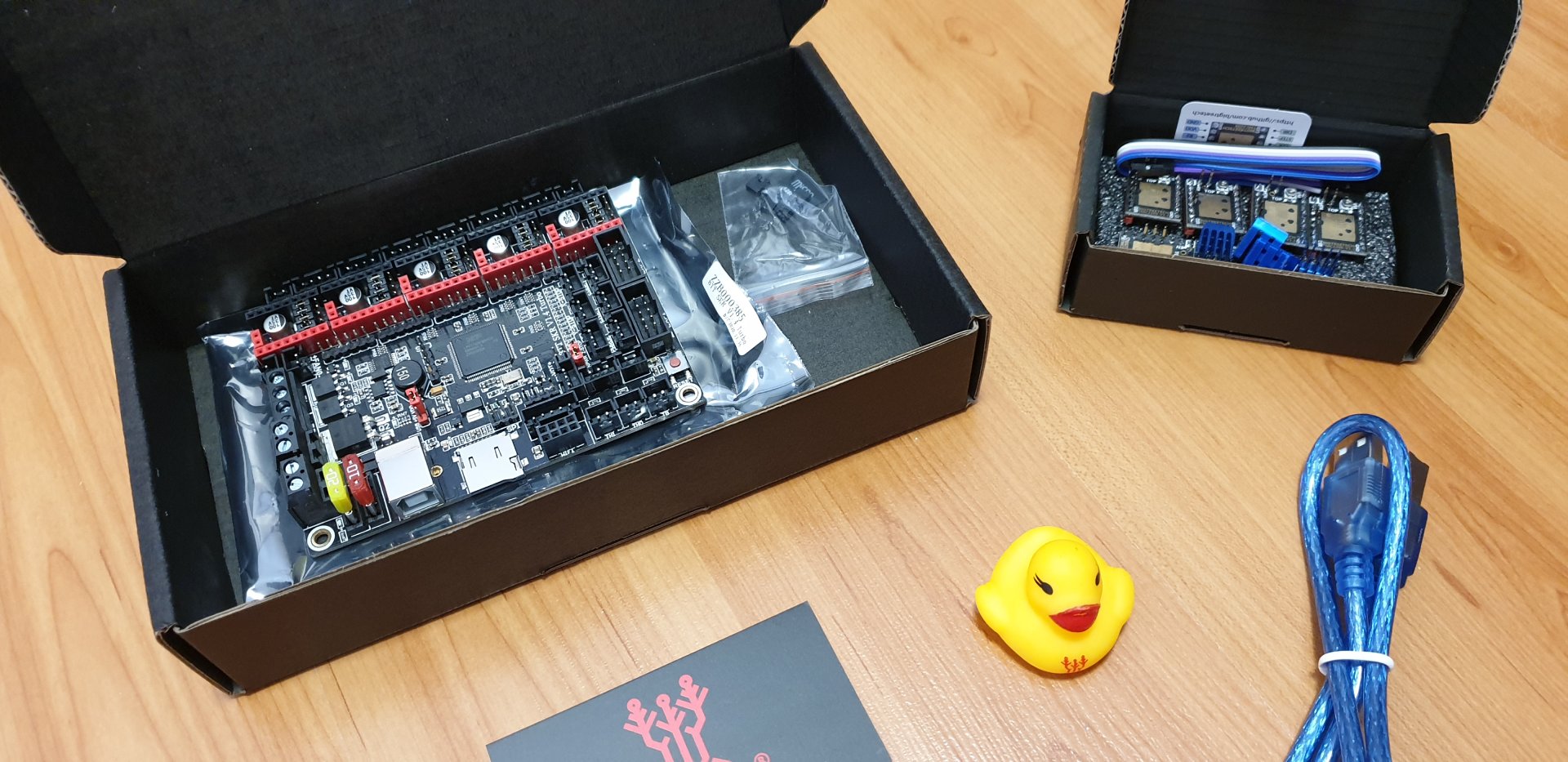
I decided to use the BigTreeTech 1.4 Turbo control board and Raspberry Pi 4B both running the Klipper Firmware to control my Inova SLS 3D Printer. If you are interested why and how I came to that, read further.
To be able to determine what I will need in terms of electronics and its overall architecture, I had to define all the components to be connected into the printer’s control system. This list is as follows:
- Galvanometers will be in place for precision (X) and (Y) axis’ moves
- Two step motors will move the powder bed (Z1) and print bed (Z2) up and down
- One step motor will ensure the recoater’s moves (R) for application of the new layers
- 5W blue laser will be the sintering power source (wavelength 445nm)
- Heating or cooling process will be controlled for
- powder chamber (by 5 control loops). I will heat each side the powder reservoir chamber separately by 200W/230V/AC heater cartridge and will control it by solid state relay (SSR) and 100k thermistor. Likewise, I will heat the powder reservoir bed by 200W/12V/DC heat pad, regulated by powerful 30 Amps MOSFET and 100k thermistor again.
- print chamber (by 5 control loops). Same setups like in the powder chamber.
- print area surface – by 4 control loops. Four independent halogen or IR heater regulation loops with the infrared thermo-camera (giving output matrix of max. 32 x 24 values).
- 4MP on-board camera will be the mean for the real-time printing process control
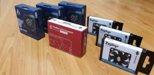
- Two groups of fans will cool the electronics
- One group for pulling the air out
- Second group for pushing the air in
Hardware requirements
Looking at this list I can summarize requirements placed on the printer’s control hardware interfaces. It must accommodate at least:
- 3 step motors and their drivers for Z1, Z2 and R axis. I decided to use the latest TMC 2209 drivers because of their quietness and power. I also intend to use the sensor-less homing functions
- interfaces for driving X and Y axis by galvanometers
- number GPIO interfaces for the heating system and for fans. It means 10 GPIO pins for chamber heaters, 4 pins for print area surface heaters, 2 pins for fan groups (air in/air out), pins for IR thermo camera
- PWM regulation possibility. I need at least one hardware PWM pin for the laser power regulation and software PWM abilities for the heater’s power output regulation
- interface for the on-board camera
- interface for the touch screen LCD
- I2C and SPI bus interfaces for internal communication
Control board candidates
It did not surprise me that it won’t be possible to use any off-the-shelf control board commonly used for FDM printers. I was also not aware of any directly available and dedicated for the SLS printers. To serve all the peripheries I had to put control hardware together from various components based on the analyses of the off-the-shelf FDM control board features. A had a deep look mainly at:
Joined sign of all these boards is the 32-bit architecture I definitely wanted for my printer. Reason for that was the expectation of the complicated software operations. So, I wanted to have enough computing power available.
Firmware candidates
Of course, it is not possible to deal with the control board without the thoughts on the firmware, so I did it in parallel. Here is my firmware list I dealt with:
For both control board and firmware selection, I went through the documentation of listed candidates in huge detail. Problem was I was not sure I am able to list down all interfaces, features, etc., I will need at the end. Therefore, I wanted to have the architecture somehow open for future expansion.
Actually, this was my key requirement while analyzing particular firmware. For that fact I didn’t stick just with documentation. Deep dive into each firmware’s source codes was needed. I wanted to see which features from my list are implemented and which not. In addition to that, the code structure and programming style played a role when estimating efforts for firmware customization/extension. Last but not least I focused on the programming languages used.
Final setup
Based on the individual findings we chose the final configuration:
- BTT SKR 1.4 Turbo (BTT) as the control board running the Klipper firmware
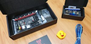
- Raspberry Pi 4B, 2GB RAM (RPi) as the secondary micro controller unit (MCU) running Klipper firmware and hosting the front-end server
where these boards are connected via USB.
What did we miss?
Unfortunately, even this setup is still not allowed to connect all the heating system components as well as the galvo drivers. The only solution how to do it is to design own PCB board. Unfortunately, I am not the best in this field. So, I am working on that (and on programming as well) with my good friend. He found company called JLCPCB which makes nice PCB based on your schema within a few days, for a few bucks.
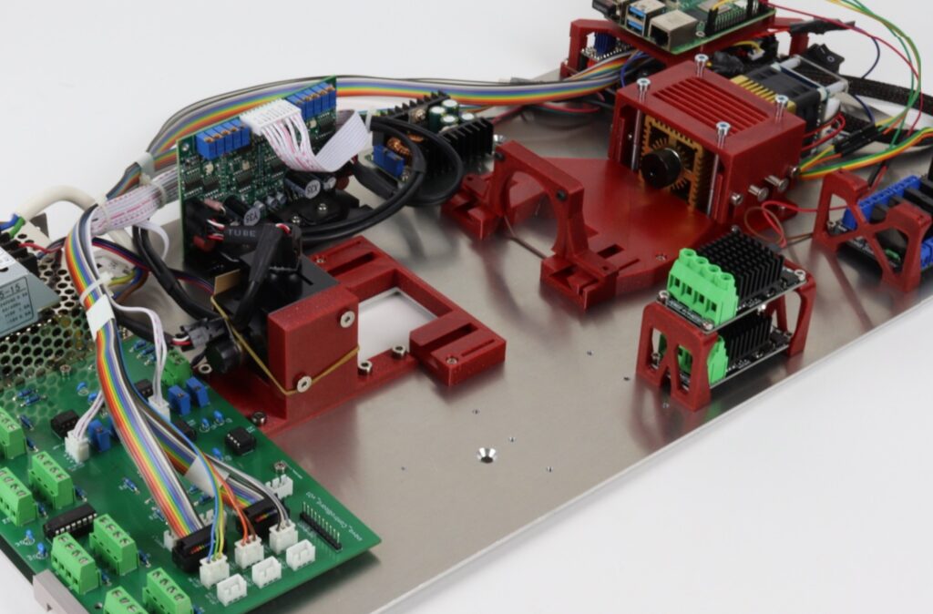
And – here it is. This is our Inova Control Board v01.

Despite, the v01 version of the Inova Control Board is not the prettiest and the most effective PCB design in the world, it works. Nevertheless, the list of changes and improvements for v02 already exists and still evolves. I intend to fabricate it immediately after the printer will pass the complex printing tests and related tuning. By that time, the v01 can ensure following functions:
- read temperature data from up to 16 thermistors
- control galvo drivers for (X) and (Y) axis using 16-bit DAC
- finetune galvo control voltage range (+-5V)
- directly control up to 4 MOSFETs
- switch up to 8 solid state relays
- and of course, to communicate with the Klipper firmware running of BTT – via SPI bus.
As you can see, this early version was not capable to control number of heaters I needed. But I didn’t intend it like this. It was mistake when I controlled the PCB specification – I overlooked that. So, just as many times before we had to found reasonable solution.
Initially, we thought we will need the v02 immediately, but we figured out another way. We changed our Klipper firmware configuration to be able to control everything what needs GPIO directly from RPi. Now the BTT board sends signals for steppers, galvos and laser control only.
Galvo & Laser selection
Selection of the galvo set was chapter for itself. Problem was that to use galvo in this project is non-trivial, what I didn’t see or didn’t want to see, until I began with some initial testing. To shorten it – to buy the cheapest galvo set (see picture below) available was definitely not the best approach.
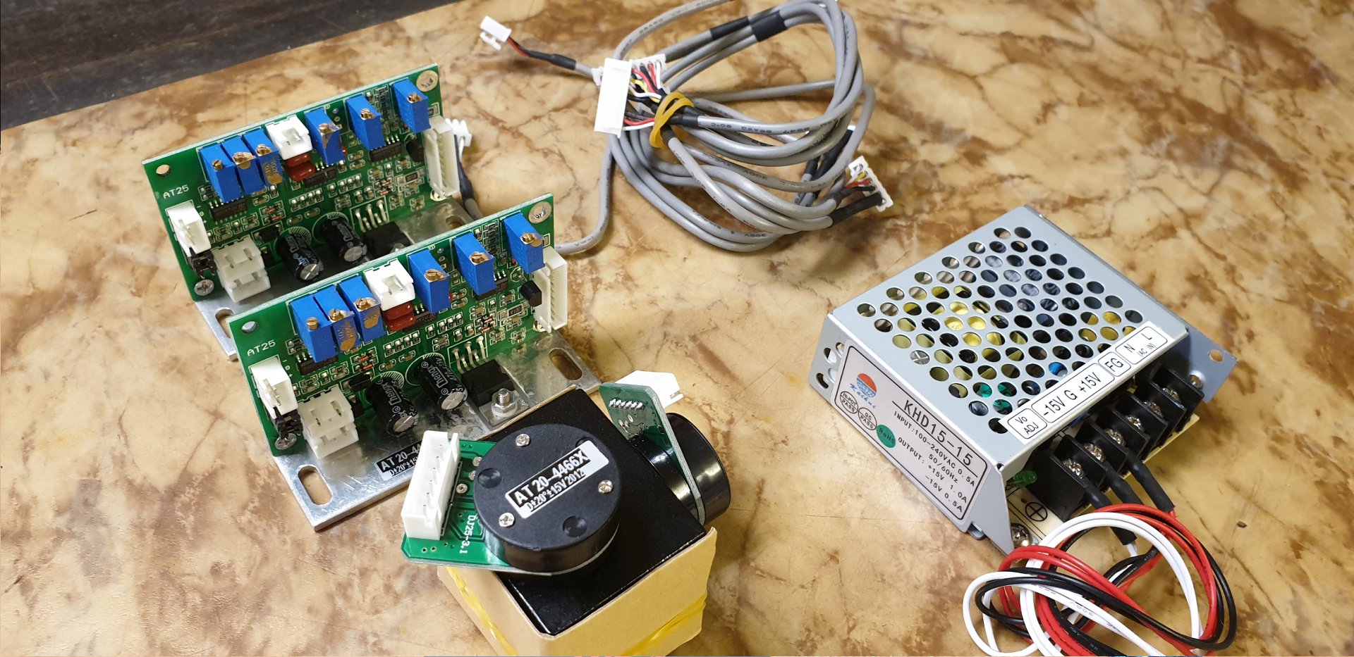
Basically, it worked OK for the purpose it was developed – laser shows. But the impreciseness of (X) and (Y) moves (caused among others by low grade PID regulator) made it unusable. Finally, I ended up with the Dragon Tiger’s DT-40 which seems to have good value for money ratio.
Unfortunately, it was the same story with the laser – I will give you detailed information in the separate post. Important is, after a few mistake selections I ended up with this 5W LaserTree module, which works fine.
Theoretical max. power input
If you calculate the total electrical power required to run the printer, you arrive at a pretty scary number. Theoretically, it can reach maximum values approaching 3,000 W. This figure represents the total power of all components working together at maximum.
It was possible that I won’t need 1,000 watts of power to heat each chamber, but I didn’t sure. That’s why I wanted to have enough power to find the optimal settings when testing. I’m always rather on the safe side, where I don’t have to use all the available power, but I can.
The other thing is that the printer preheats as part of the preprint sequence. That, together with the subsequent controlled cooling of the printed parts, strongly affects the overall print time. Therefore, I plan to play around with the heating characteristics to get the optimum power consumption setting along with the overall print speed.
Electric power sources
There are 3 different power source types on- board. AC 230V as the main electricity supply will be used to directly feed the cartridge heaters placed at the chamber’s sides. It is also used to feed 2 power supply units which have to be on board.
First is DC 12V/600W (50A) PCU needed for all the control electronics and the powder and print bed heating pads. Power for RPi and connected LCD is taken from the buck convertor changing DC 12V to rock solid 5V. Second PSU ensures the electric voltage for the galvo set which is running at DC +-24V.
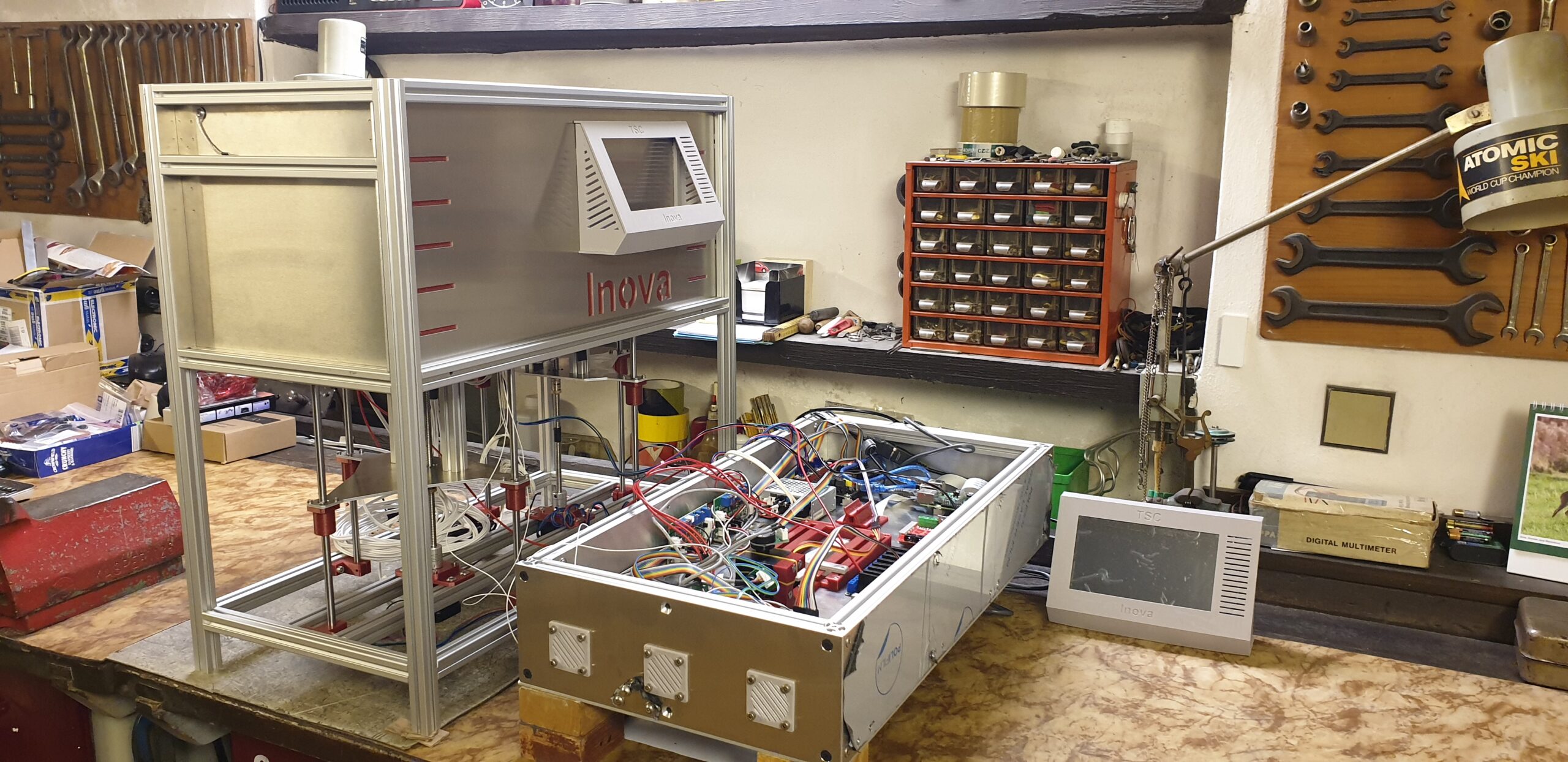
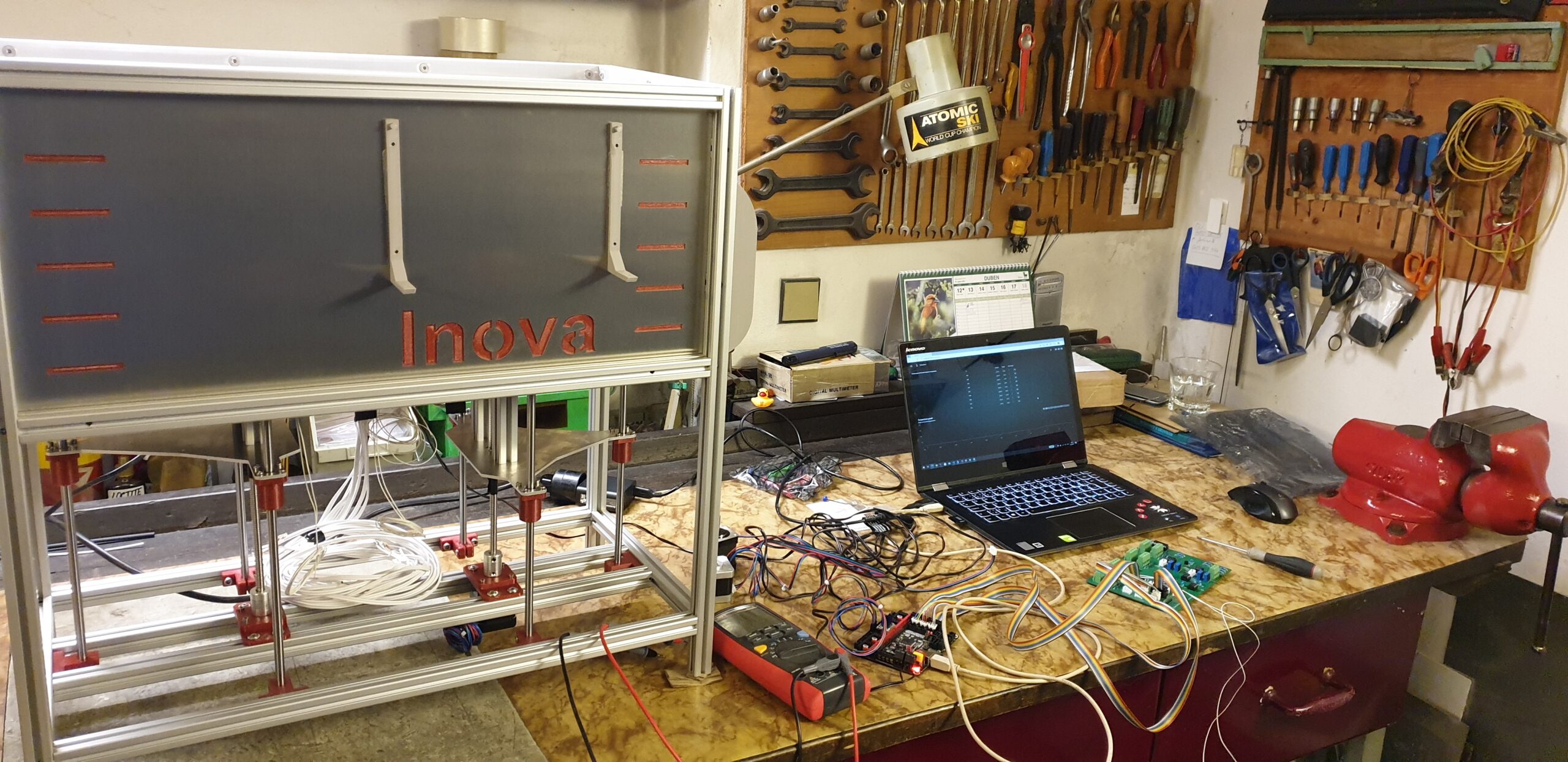
As I am writing this post at time when I have already known this setup is working together quite OK, I expect no major design changes. I had faced several smaller or bigger problems during initial testing, but all of them were successfully sorted out. In gallery are for fun also two old pictures slightly uncovering how it went through 😉
I will tell you how I wired everything together in the post focused on the electronics interconnection.
—
Join us on Discord