Initial design as well as the electronics setup and firmware selection were behind me so I could move to the Inova build itself. Although it took me a few months to get to this point, now I can shout: “Yes, let’s the fun begin, heated chambers and beds are waiting!”.
Those words did indeed run through my head, but the spontaneous joy was rather quickly replaced by a long series of doubts. I have studied a lot of documents related to the laser technology, sintering process and other important topics during the design process. And the more I began to know, the more felt I had taken too big bite. So, on the crossroad again where I had to make “go/no-go” decision. It was harder than at the beginning. From now on, it will cost not only my free time, but it will burn my money as well.
Never mind, let’s go for!
Build process was strongly influenced by steps order I did during the design stage. Therefore, I decided to start with the fabrication of the chambers (print and powder reservoir). Print chamber’s role is to form the total print volume for printed parts by dividing it into the separate layers. Next, even more important function is preservation of printed parts against unwanted shrinking and warping. To ensure this feature I must the chamber to heat and well thermo-regulate. Therefore, each chamber’s side has its own heating element equipped with thermistor.
Preparation of construction parts
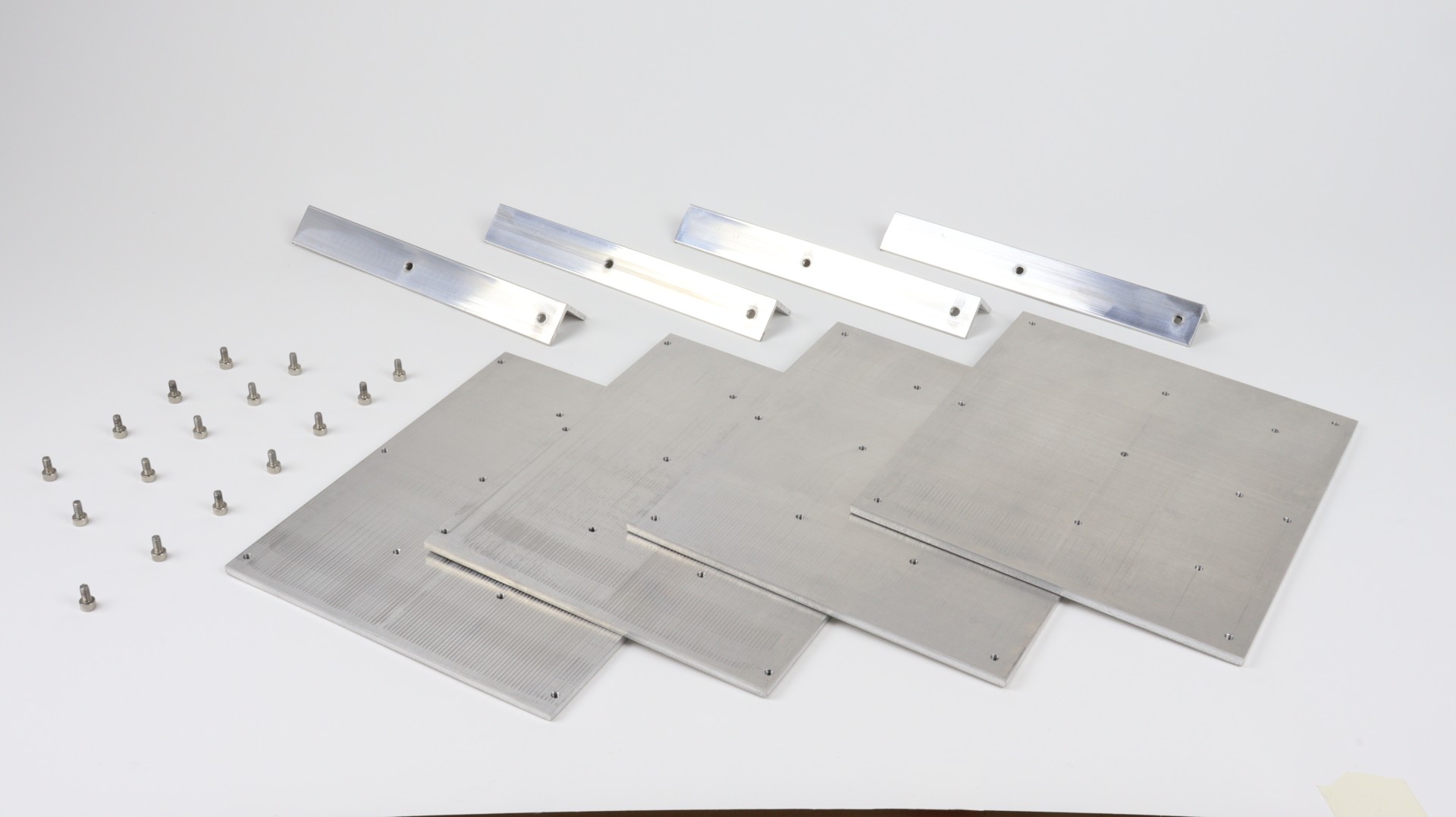
Main material of the printer are aluminum sheets and extruded alu profiles 2020. I made from that not only chambers but actually all the frame construction as well. But I will write something about the frame production and its build later on.
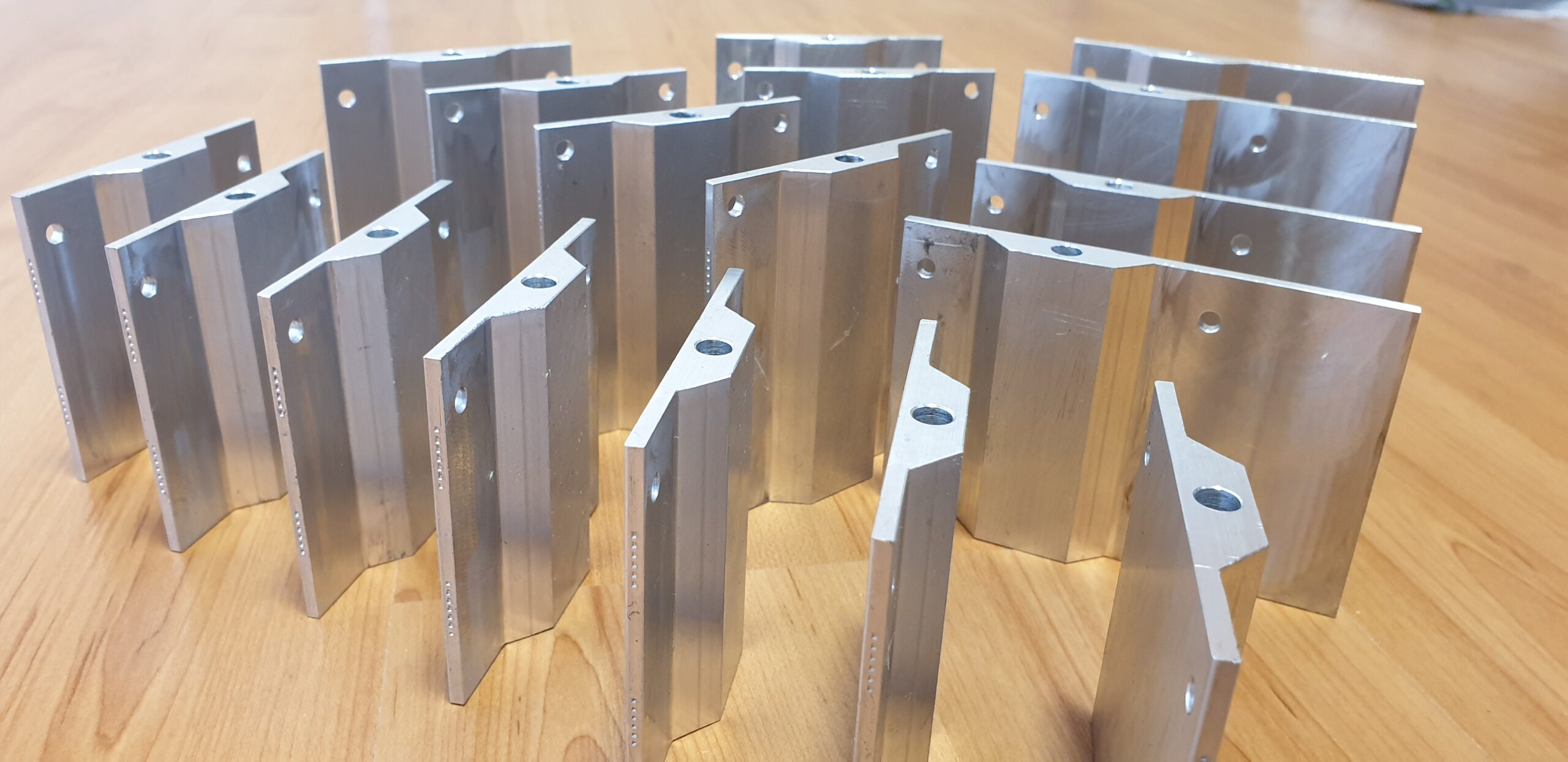
To have everything perpendicular a precise I decided to cut alu sheets on the laser CNC machine. It also saved me a lot of time because I included into most of holes for threads. I was really happy with the result. Before the build itself I just had to sand the edges and made M4 threads.
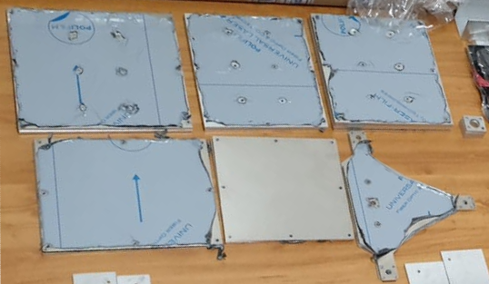
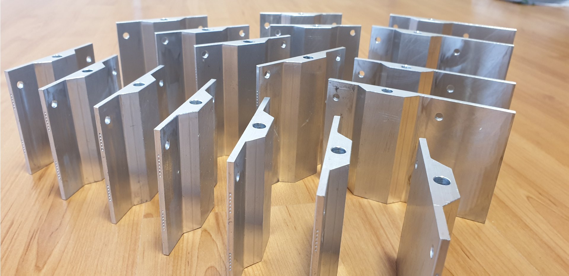
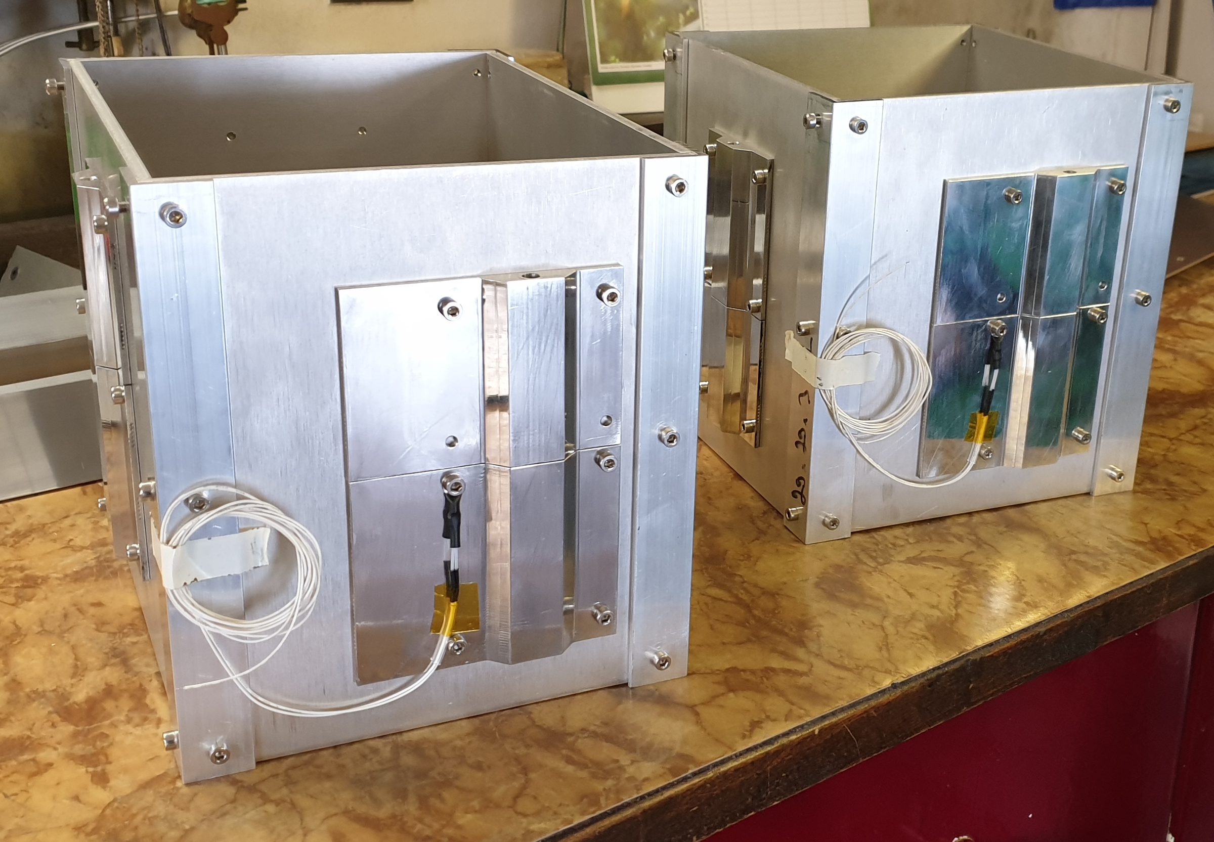
Each side of the chamber has really a lot of threaded holes. These have two different purposes. Holes nearby the edges hold the chamber together thanks to four alu L-profiles (25x25x3mm). The rest is for something I call heating blocks.
I made them on the CNC mill from the 10mm aluminum plate to make housing for AC230V/200W heating cartridges. These have 6mm diameter and their effective heating length is 150mm. Surprisingly, this length was the problem. Reason is, that it is tricky to bore such a deep hole into the “muddy” aluminum. To sort it out I decided to divide each heating block into two parts. I was not ideal, but it helped me to move forward.
Build process
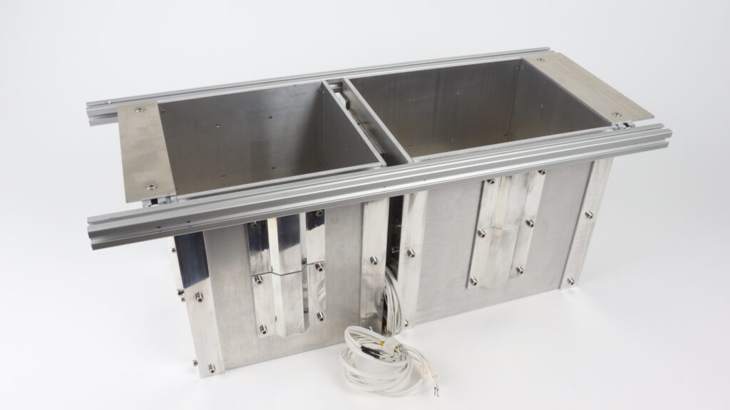
Chamber build process itself was simple. Four 5mm aluminum plates form the shape of heated chamber which is hold by L-profiles (chamber side connectors). All I needed to do was to screw all these parts together. I used 8mm long M4 screws to avoid screws sticking out of the chamber walls. These fitted for both side connectors and heating blocks.
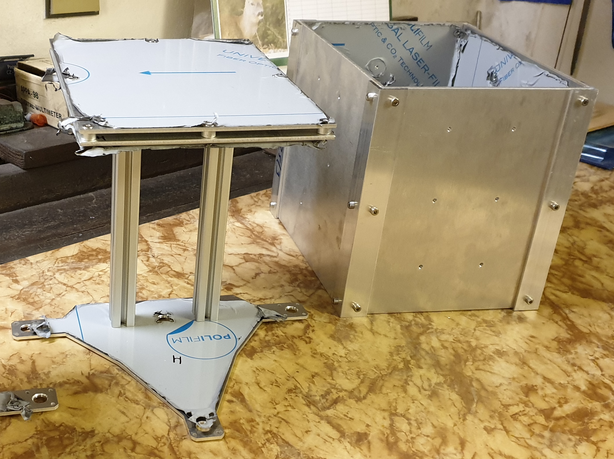
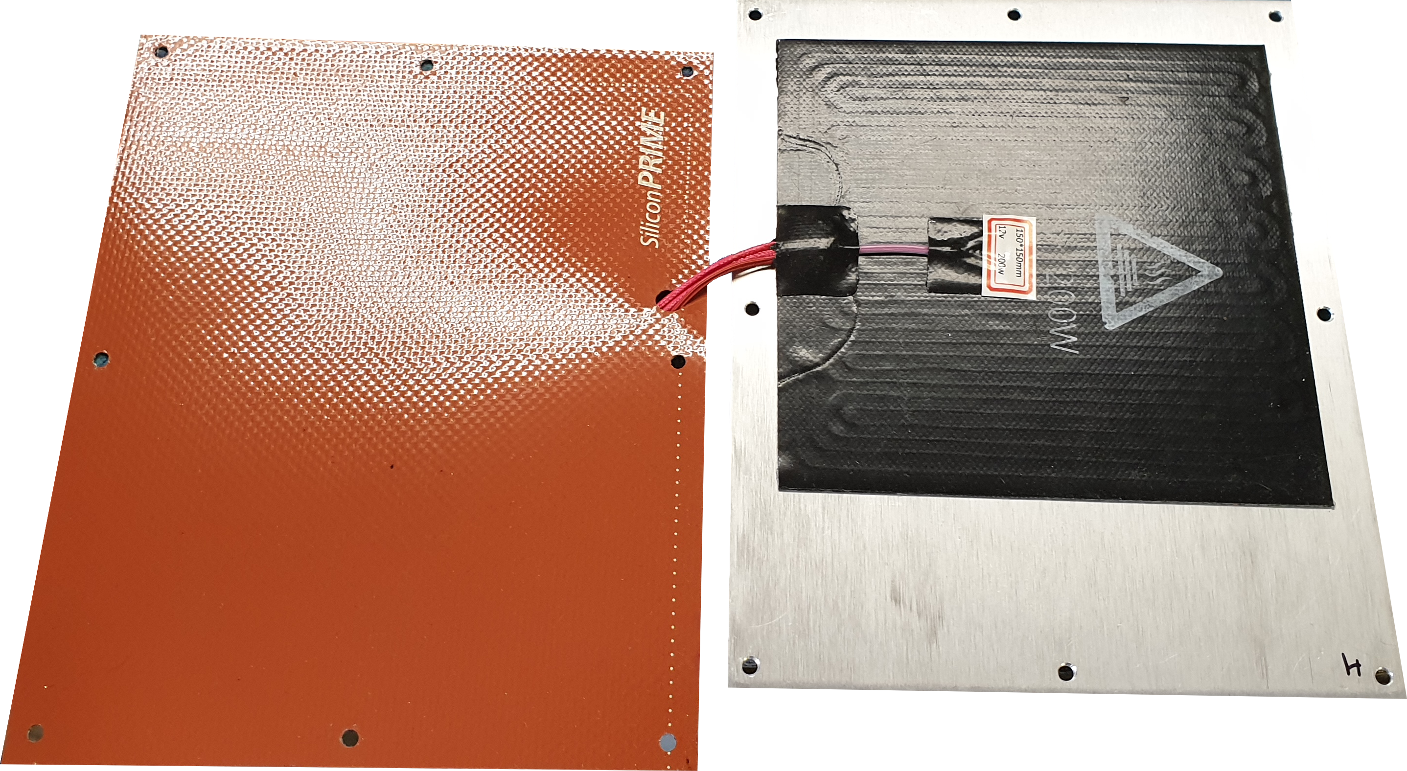
I made the whole print bed assembly from three 3mm alu plates and two 2020 extruded alu profiles. Top two sheets are the bed itself. I doubled it because not only the chamber sides, but also the print bed is heated. It utilizes the 150x150mm DC12V/200W silicone heating pad. It is the same kind which use the FDM printers for their print beds. In between plates are spacers that limits the spread of the heat.
Next part is the silicone sealing acting as the powder wiper on the heaeted chamber walls. See picture below showing the top part of the powder supply bed instead of printer bed, but principle is the same.
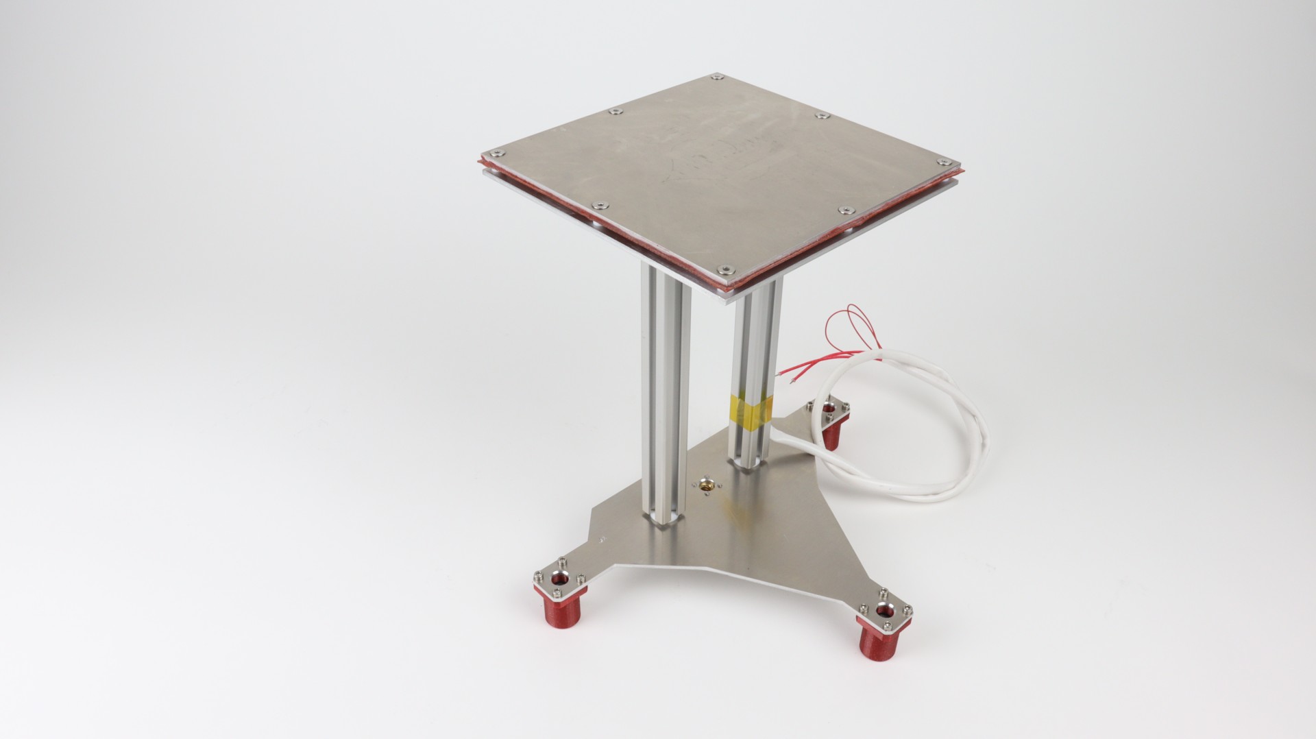
Bottom of the print bed is prepared to be joined with the linear motion parts. It holds three 3D-printed linear bearing holders (printed on my PRUSA MK3s) for common LM8UU linear bearings and one 8mm trapezoidal nut. All these parts are connected to the bottom bed plate using the set of M3 screws.
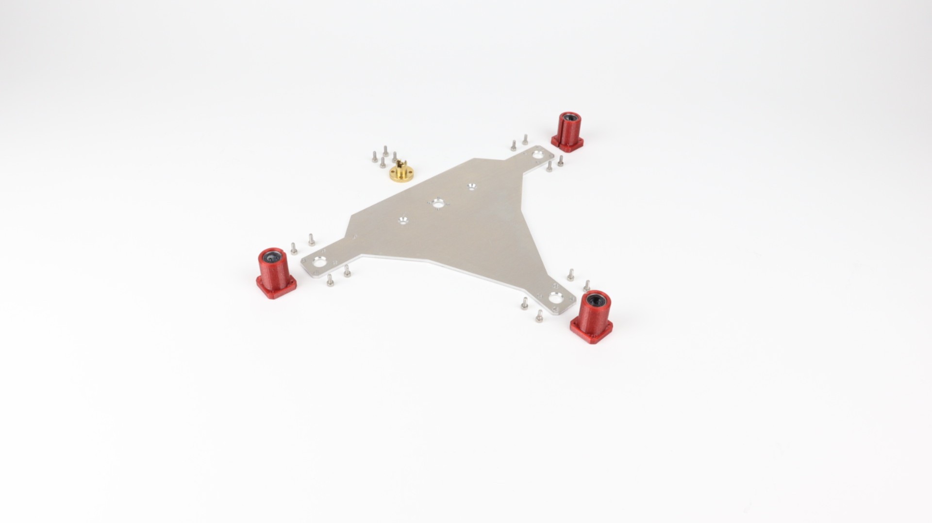
Top and bottom part of the print bed is connected by two 2020 profiles with M5 thread. It was second reason why I doubled the top part of the bed.
Design adjustments
After some time, I had to change the construction design a bit finally, as compared to the picture above. It related to the heat spread prevention. Side connectors are now shorter to make room for the Teflon (PTFE) insulators. Spacers between print bed plates are made from PTFE as well.
Construction of the powder chamber reservoir was the same as the print heated chamber, so I repeated whole process once again. I was just using different sizes of chamber/bed sides all the rest was equal.
I was quite happy with both chambers and beds (see all build and workshop photos). So, I ordered a material for the recoater assembly which I planned as my next step.
—
Join us on Discord