I’d like to continue in the topics related to the optics used in my laser sintering printer. In my last post I have already touched the problematics of the suitable laser sources, described why I choose the laser diodes instead of e.g. CO2 lasers, how does the beam shape look like and how to change and collimate it. I ended up with the finding that my laser beam shape is too small. So, I’ll continue from this point.
The size (“diameter”) of the beam is important, because the larger the input beam, the better focused spot quality. Therefore, I decided to expand it.
Beam expansion
Beam expansion can be done by several methods. I have already tested the one using anamorphic prisms and I really didn’t like it. Later, I found the solution which suits me better. It comes out from the theory of telescopes.
There are two main groups of telescopes – refracting and reflecting – where the groups’ names are self-explanatory. Reflecting (also called Newtonian’s) telescopes use mirrors to reflect the light, refracting ones utilize lenses to bend or refract it. Actually, there is the third group called catadioptric telescopes which is the combination of the previous ones. It is fairly popular because it sorts out their cons (off-axis and chromatic aberrations). As I use the refracting telescope principle, I will look at it in deeper detail.
Generally, the reason for using beam expanders is the need for:
- reducing the power density of the laser source
or
- minimizing the beam waist radius at longer focal distances
Telescope expanders keep the in/out beam energy nearly without any change. The beam area increases then quadratically with its magnification ratio (read further for explanation). This is pretty nice feature which enables effective energy density reduction. Because of that you can achieve longer lifetime of the optical components like mirrors, etc. You may think how can this be beneficial for the laser sintering in Inova SLS printer? And you are right. It does not make a lot of sense while using relatively low power laser.
But there is the second characteristic. If you increase/expand the diameter of the laser beam, you can better focus it at longer distance, which is great. Principle is simple. Telescope just expands the input beam by the magnification ratio. Simultaneously, it decreases the beam divergence, again by the magnification ratio. Both these facts will make the focused output beam diameter smaller at larger distance.
Keplerian telescope
Basically, you can choose from two arrangements of the refractive telescopes – Keplerian or Galilean. They both can do the same job and as with anything, each approach has its pros and cons.
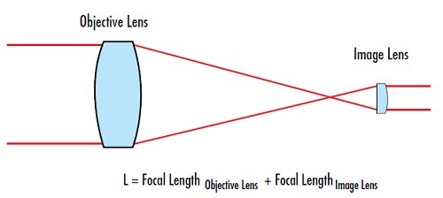
Both telescope’s arrangements are very straightforward. The Keplerian telescope uses two double-convex or ideally plano-convex lenses in the line. In my case (I want to expand the beam), I use the one with smaller focal length just behind the laser module’s collimating optics. Currently, Inova uses the plano-convex lens with the focal length of 13.5mm (FL1). That is followed by the second plano-convex lens with the focal length of 40.5mm (FL2).
Note: Convex side of the lens must always face the collimated beam to reduce spherical aberration.
I think now it’s a good place here to explain how the magnification ratio is calculated. Again, it is not complicated at all because it’s the simple ratio of the FL2 and FL1. So, in our case it is 40.5/13.5 which represents magnification ratio of 3. It means that, when I have got collimated beam going from the laser module into the expander of approx. 2.5mm in diameter, I get approx. 7.5mm diameter as the output.
I also had to count with the size of mirrors in galvo system while expanding the beam diameter. Actually, I overlooked it for the first time and had some headache because of that afterwards. Current lens setup is the real maximum of what is Inova SLS printer able to accommodate dimensionally. I plan to change it a bit – to the magnification ratio around 2.5.
Galilean telescope
The optical principle of the Galilean arrangement is the same as the Keplerian one. The only difference is that it utilizes one plano-concave and one plano-convex lens. As you can see on the following image, main advantage lies in the mounting space requirements reduction.

Since the Galilean telescope uses plano-concave lens which has negative value of the focal length, it needs smaller mount space. As a result of that, if you use the same magnification ratio and the same focal lengths, Galilean setup is shorter by two concave lens focal lengths. In my case is the theoretical lens distance 54mm for Keplerian and 13.5mm for Galilean telescope.
Another quite important advantage of Galilean version, as compared to Keplerian, is there is no internal focus point. It means this arrangement can easily handle high optical powers with just a small generation of unwanted heat. On the other hand, you lose the possibility to place spatial filters into the internal focus point.
Currently, I use the Keplerian telescope arrangement in the Inova printer. Reason for that is prosaic – I didn’t have suitable lenses for Galilean setup. I don’t know why but it is much easier to find convex lenses than concave ones. But I plan to try Galilean telescope for laser sintering in the future.
Beam focusing
Another operation you have to undertake with the laser beam is to focus it. This step makes the laser beam diameter smaller and increases the energy density. Thanks to that is Inova capable to do laser sintering and to make desired 3D parts.
When I got to focusing the beam, I considered the following approaches:
- F-theta lens
- Simple plano-convex lens
Focusing using f-theta lens
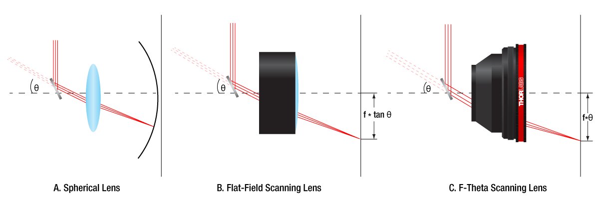
What actually is the f-theta lens good for? In simple words, it is the piece of optic used for precise scanning of the flat surfaces.
Combination of galvo and common spherical lens results in the spherical shape of the focused scanning field. Therefore, in case of flat selective laser sintering printer bed, you can achieve focused laser beam just at one point (in the center of the bed) or at one circle of defined radius. As compared to that, f-theta lens ensures to have laser beam focused across the whole bed. It is important because it keeps the energy density/beam size constant while moving along the bed. Following picture should help you to understand it. If you want to know more look directly here.
Dark side of the F-theta lenses, from the Inova printer perspective, is the price, size and the common antireflective coatings.
Prices are normally in hundreds of EUR or USD. When speaking about the size it is around 100mm in diameter. You also need a long focal length to cover reasonable print area and it would make printer huge. Last problem is the AR coating – I didn’t find hardly any f-theta lens suitable for wavelength of 450nm. So, these are my arguments why I didn’t use it even I know I should.
Focusing using plano-convex lens
I can’t find a lot of arguments to use simple plano-convex lens for the beam focusing in the selective laser sintering printer. If money and printer’s size is not a problem, the best way is to utilize f-theta lens with the appropriate AR coating. But unfortunately, it is not my case. I had to find the way how to do it using simple and cheap lenses.
When I was playing with the anamorphic prisms, I placed plano-convex lens with FL 300mm just behind them. It worked quite OK – I mean it focused the beam as expected. The only problem was to control the beam expansion ratio precisely and to direct it into the center of lens. As I said last time, it was the nightmare to set it up correctly.
Then I moved to Keplerian telescope, and this problem disappeared.
By now, I spoke about telescopes just in relations to the beam expansion. But you can use them to expand and focus laser beam in one step and that’s just brilliant. You can make it by increasing the distance between the lenses (L1 and L2). Therefore, as you can see on the picture below, these two lenses are the only things I use to expand and focus beam.
And how I handled the beam defocus causing the beam shape and size is changing across the print bed? Optically/mechanically it was no way. I tried several approaches how to change focal length automatically, but I was unable to make it good/precise enough.

So, I ended up with the software algorithms in the slicer which take this into account and compensate it. It seems to be a good way, so far.
Galvo’s principle and parameters
Galvos, alias galvanometers, are used in Inova to move laser beam along the X and Y axis. These moves are done by changing the voltage going through the coil inside the galvo. It changes the magnetic field and causes rotation of axle which holds the mirror. In principle, therefore, the bigger the voltage, the bigger angle of mirror rotation.
Since the voltage changes can be quick, mirror moves can be pretty fast as well. That’s one of the reasons why special electronic drivers are used to ensure moves’ preciseness. When speaking about the preciseness, most nowadays galvos are closed loop systems. It means that driver sends position signal to the galvo and galvo gives feedback about its real position. It is done optomechanically – photodiodes and LED are in place.
Light going from LED to the photodiodes is partially blocked/shaded by the plate connected to the rotating axle and mirror. Light intensity itself than represents this feedback which is equal to the mirror position. PID controller is also the must as you have to deal with the centrifugal forces on mirrors, friction in bearings, etc.
Galvos are characterized mainly by:
- Max. mechanical deflection angle: normally +-15°.
- Speed: expressed in kilo points per second (kpps) at given deflection angle (normally at 8°)
- Signal voltage: normally +-5V or +-10V (yes, you need both positive and negative potentials)
- Power voltage: normally +-15V or +-24V (again, you need both positive and negative potentials)
- Size and AR coating of mirrors
Inova uses DT40 galvo which has following parameters:
- Max mechanical deflection angle: +-15°.
- Speed: 40kpps at 8°
- Signal voltage: +-5V
- Power voltage: +-24V
- Size and AR coating of mirrors: 7x12x0,8mm, suitable for wavelengths 400-700nm

Galvo related issues
I faced several issues while testing galvos. When I used a cheap galvo-set I had a problem that it was unable to make precise moves. I tested it by burning gray paper and e.g. instead of circle I always get something like open ring – start and end of the circle didn’t match. In my opinion it was the issue of the PID regulation, but I wasn’t capable to tune it. I have tried several cheap sets, and it was always the same. This problem vanished with the DT40.
We had also some problems with the SPI bus interferences caused by incorrect interrupts – it was our fault in FW implementation. But since this is more of a SW/HW topic, I’ll save it for another post 😉
—
Join us on Discord
dear friend!I’m afraid that the optics scheme you have chosen is wrong because it has a long beam length to the focus point.Since the crystal of a semiconductor laser has a size of less than one tenth of an inch and it is light when assembled with a lens, it may make sense to pump the laser itself over the surface of the powder in a cooling medium, that is, the beam will draw a snake and the positioning system will move an order of magnitude slower,
Thank you for your comment.
The long focal length is the necessity in this case and is commonly used by several manufacturers in this area without significant problems. My tests so far have turned out well too.