Frame of the Inova SLS 3D Printer is not the most complicated thing in the world. But despite that, it still has to fulfill some specific requirements. Biggest challenge was to design the printer frame in the way to accommodate all the heated parts and at the same time to hold the heat only in frame areas where is needed. Here are several reasons for that:
- Printing material must be preheated before printing in both print and powder supply chamber (for PA12 to approx. 145°C).
- Preheat should not be longer than needed. It means not to wait for prints longer than it is necessary.
- After printing, cooling process must be well regulated to avoid warping and shrinking.
- Keeping the heat inside the printer will make the heating process more effective and cheaper form the operating costs perspective.
- For safety reasons, the frame must not be hot to touch it.
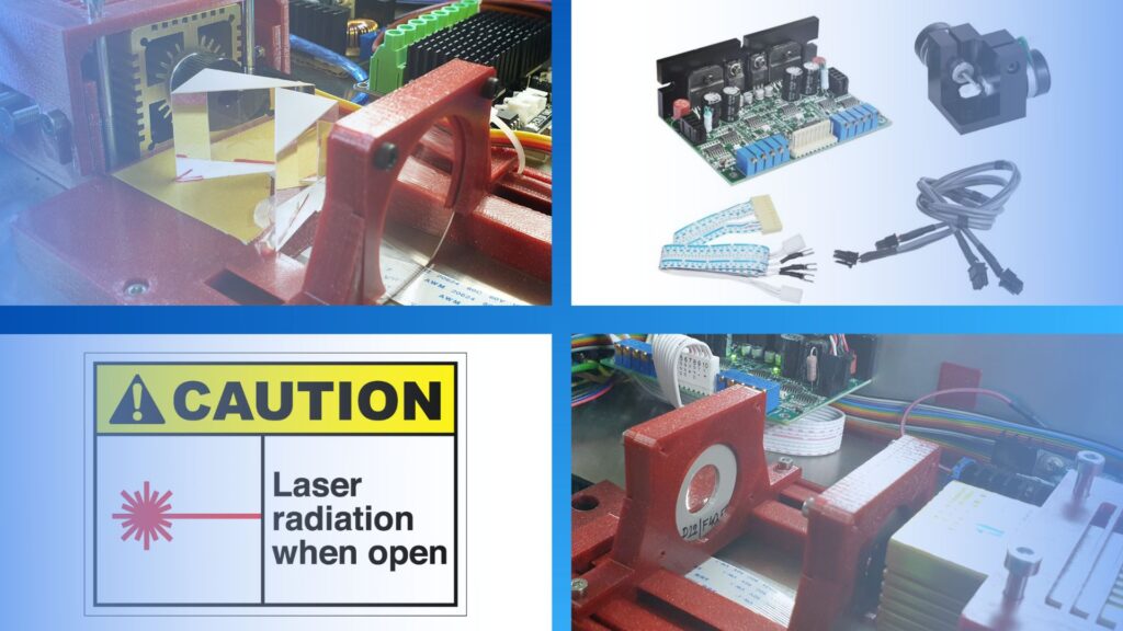
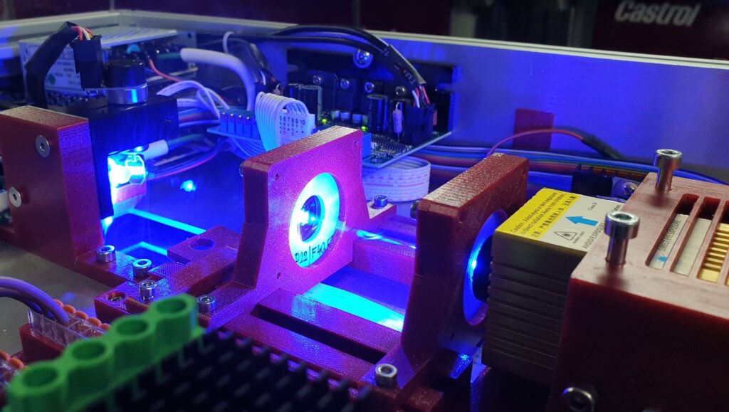
I believe, all these arguments are quite clear and understandable. The only thing which complicates it a bit is electronics’ heat protection. Reason is that galvos for instance are sensitive for operation temperatures. If temp goes up, galvos start to drift and to lose their move’s accuracy. The same is it with laser diode which goes out of power with the raising temp. Raspberry Pi and BigTreeTech Board are also not fans of high temps. Therefore, the only way how to achieve desired frame features was to propose it as double-skin. Powerful ventilation for electronics is must as well.
Used materials
From the material selection perspective, I decided to use combination of 2020 extruded aluminum profiles with the aluminum sheets. These sheets are 3mm thick, which can be a bit too much, but is has the reason. I needed enough material for making threads for many different holders, covers, etc. I also wanted to have the construction rigid enough.
Teflon (PTFE) spacers (3mm thick) will remove majority of heat bridges among the inside and outside parts of printer frame. That is because Teflon is great heat bridge destructor. Just compare the ability to lead the heat of the aluminum and Teflon. You find out it is approx. 230W/m/K for aluminum and 0,24W/m/K for PTFE which is enormous difference. Similarly, Rock wool, as the second insulating material, is simply everywhere between the heated internal parts and the external cladding of the printer. Its coefficient of the ability to lead the heat is nearly as low as the air (about 0,026W/m/K).
Frame production
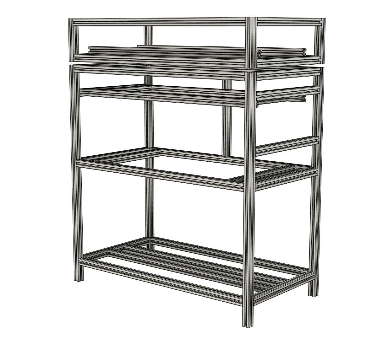
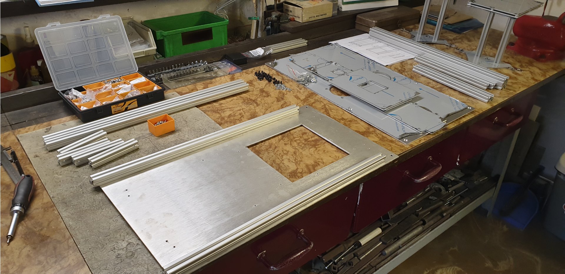
Printer frame production started with order of 2020 profiles. I counted all the lengths in Fusion360 and ordered adequate number of 1,95m long residual pieces. In fact, it has an advantage of easier manipulation in my workshop as well as better price tag (as compared to full length which is 6m). Then, I cut them to appropriate dimensions at the formatting saw. You can find the respective cutting plan as well as the exact dimensions and number of pieces needed here.
As for the aluminum plates I generated the DXF files in Fusion and let them cut at the CNC laser cutter. I was a little bit worried about the dimensional tolerances and the edge quality. But finally, I was really pleased with the outcome. Company cutting the sheets offered me to remove the frayed edges at the surface grinding machine. After some worries about the sheet surface quality, I decided to make it manually.
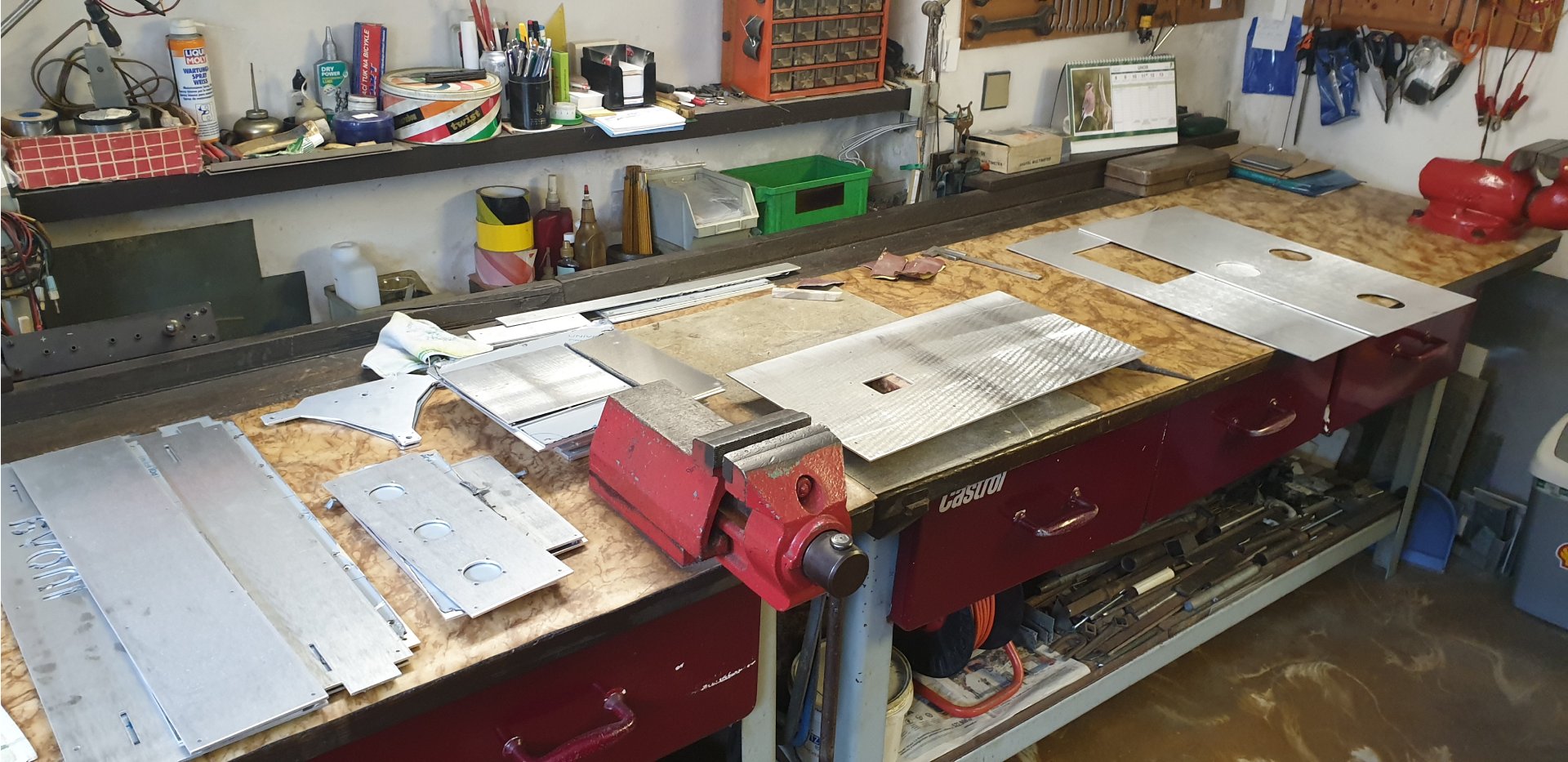
Last operation, before I was able to start putting everything together, was thread cutting. It was the most annoying part of the build because I had to make dozens of threads during whole process. First of these were M5 to be able to use the blind joints. I chose this method of building the frame from 2020 profiles because I didn’t want to use any extra connecting parts. I also wanted to have everything as rigid and perpendicular as possible. Another bunch of threads was into the sheets. Here were mostly the M3 and M4 sizes for fixing number of different holders (smooth rods, electronics, recoater pulleys, etc.).
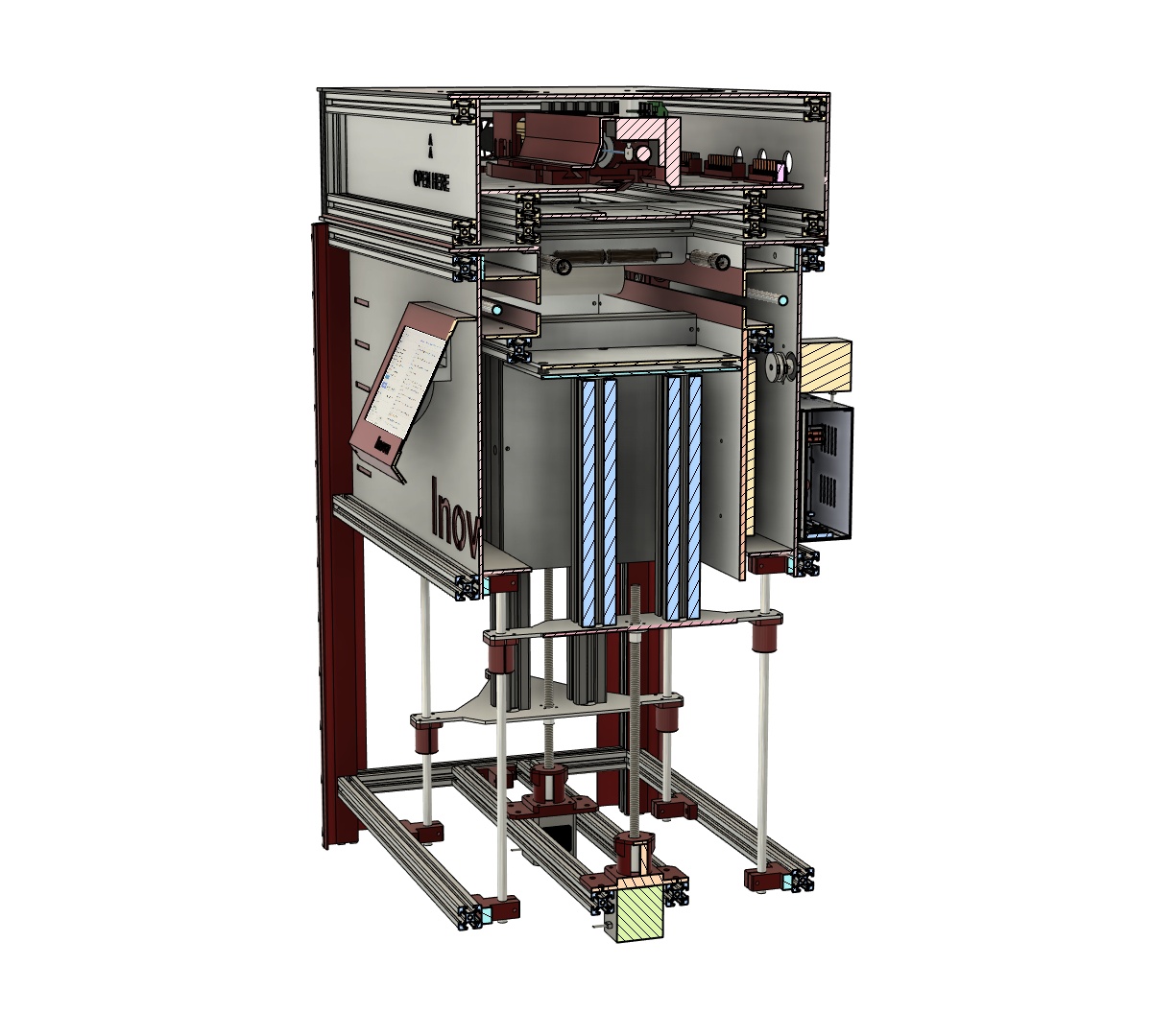
Printer frame as whole consists of top and bottom part. Top frame is the construction where is most of the electronics and optics parts. Bottom frame then forms “the housing” for the chambers and the recoater assembly.
Bottom frame assembly: Step 1
To put the frame together was not a big problem. Because I prepared everything like some kit, I just have to find the smooth and effective way how to proceed. I began with the bottom part where the main task was to install previously assembled print and powder chamber and the recoater mechanism. After several attempts I found really easy way – its principle is on the following pictures. If you want to see more detailed photos visit the workshop or build gallery.
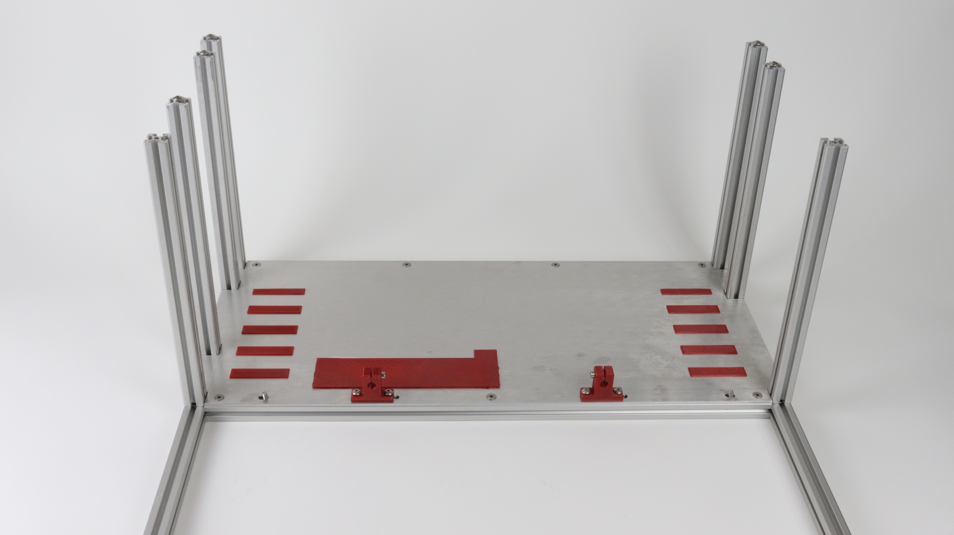
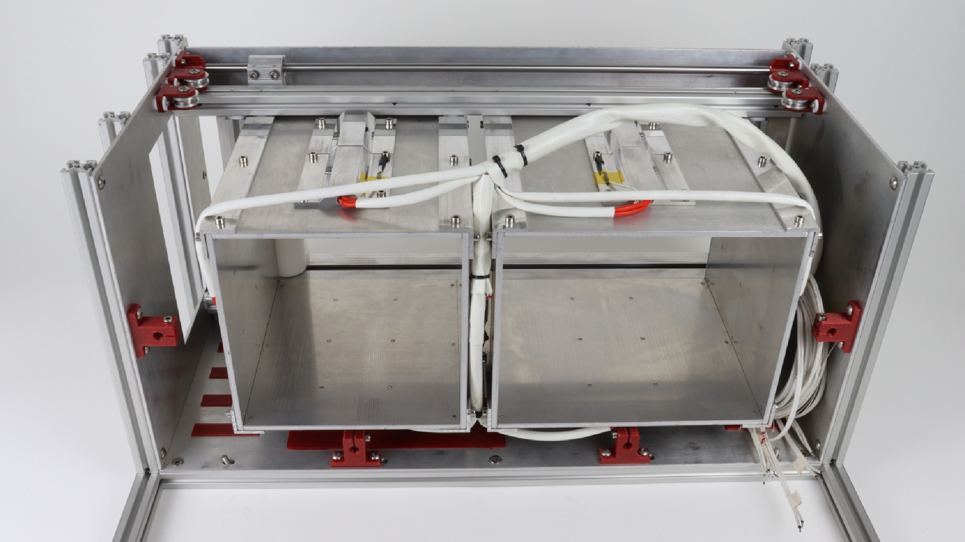
On the picture above there is the first bottom frame sub-assembly I had to piece together. As I mentioned above, I used the blind joins everywhere I could. I also don’t use the proprietary M5 bolt nuts. These are designed to fit into the profiles and hold their positions (not moving/sliding in profiles). Instead, I use the common squared M5 nuts (thin type is only 2,7mm thick) which are 10x cheaper and do nearly the same job. The only thing you must have in mind is these do not stick at the position where you place them in case of vertical manipulation. I used these nuts to join the sheets with the profiles and to hold the 3D printed smooth rods’ holders (SK8 like). The rest of the plastic pieces you can see here is just small decoration of the printer and they have no other function.
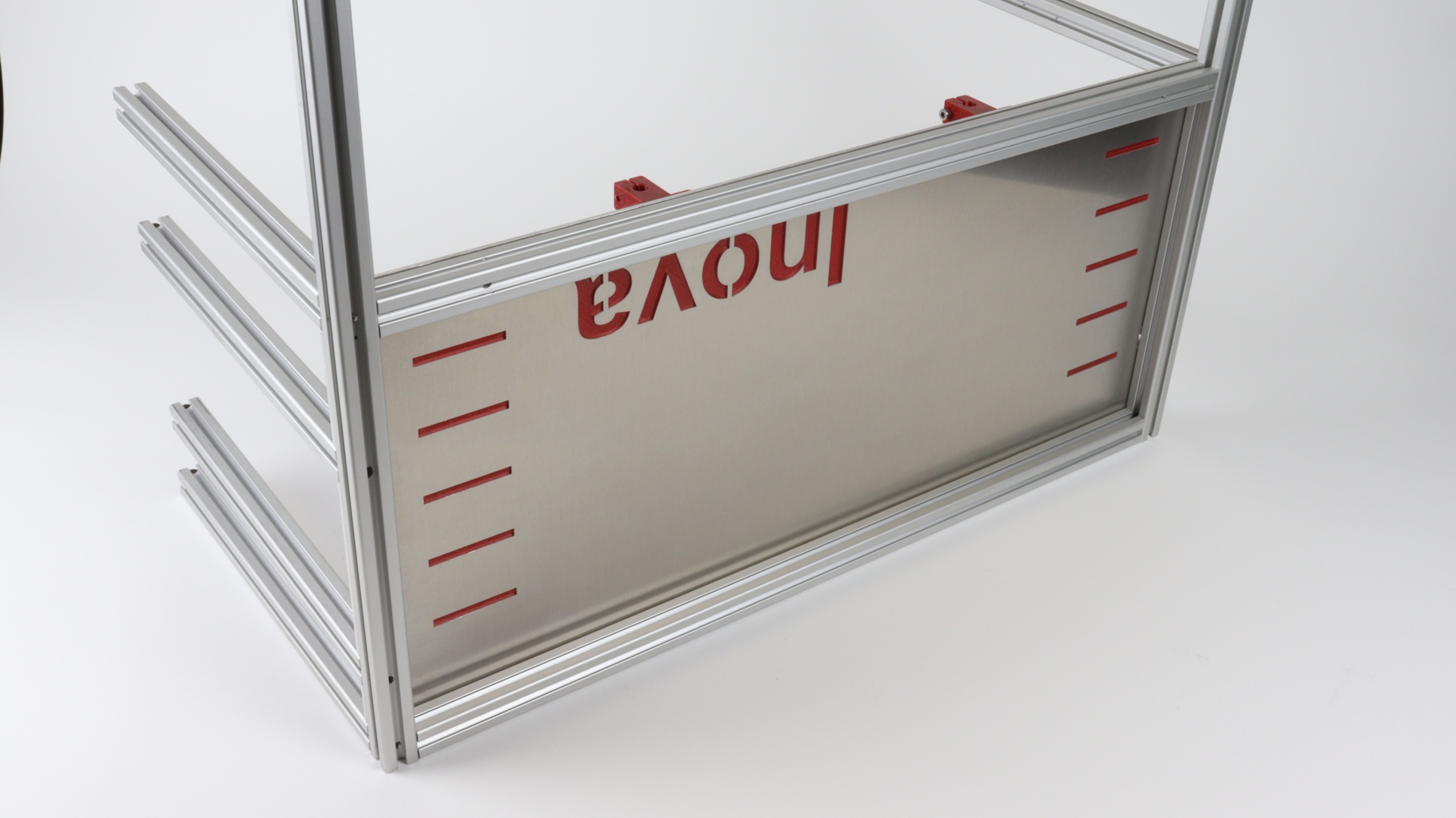
Bottom frame assembly: Step 2
Once I finished it, I inserted the complete chambers incl. recoater assembly into the frame. Again, squared M5 nuts played the main role in this step. I screwed M5 bolts gently through the aluminum sides of the chamber-recoater assembly to these nuts. Then, it was important to slide this assembly into the frame slowly to have all the nuts in the frame’s profiles.
Bottom frame assembly: Step 3
After that, I installed the back frame part. I attached the DC12 50A power supply and the stepper for the recoater. It was first time, when the initial heap of aluminum slowly began to have a shape like a 3D printer. Then, I connected the steel rope to the recoater and lead it towards the stepper pulley and back.
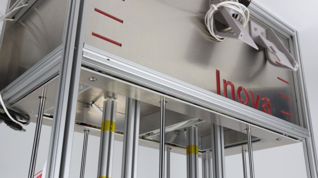
Final steps of the bottom frame build, or maybe better said of the bottom printer’s assembly, were related to adding profiles holding the Z1 (z-axis for powder supply chamber’s bed), Z2 (z-axis for print chamber’s bed) stepper motors and the related linear technics parts (SK8 holders, smooth rods, etc.). Trapezoidal screws and nuts (8mm in diameter) ensure both Z1 and Z2 moves. I am considering to replace them with ball screws to achieve better move’s accuracy, but it is on my v2 list for now.
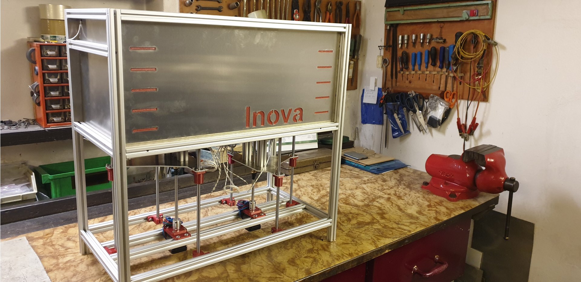
Top frame assembly
Top part of the printer frame is much simpler. It consists of several aluminum profiles and sheets to create the heat insulated home for the Inova’s brain and all the optics.
It surprised me that I’d had more problems to find the effective assembly procedure as compared to the bottom frame. As principles of build were pretty the same like in case of the bottom frame I will just direct you to the build gallery for detailed pictures which should be self-explanatory.
Note:
I would like to point out that my posts about building are not intended as step-by-step building instructions. Therefore, I have not dealt with all the sometimes tedious details yet. I have only tried to cover the key procedures involved in the build. If there is interest and, most importantly, if the printer works/prints, I will try to prepare an assembly manual in the future. I’m sure it will be for v2 though, where all the childhood diseases will disappear. On Discord you can see, for example, how the recoater turned out after deeper testing and what its current form is.
—
Join us on Discord